Show EOL distros:
Package Summary
A tool to calibrate the relative frames between the mild's laserscanner and the cameras
- Maintainer: Meißner Pascal <pascal.meissner AT posteo DOT de>
- Author: Aumann Florian, Heller Florian, Meißner Pascal
- License: BSD
- Source: git https://github.com/asr-ros/asr_mild_calibration_tool.git (branch: master)

Contents
Description
This package provides a tool to collect transformation data between the mild's laserscanner sensor and it's camera head. This data can then used calibrate the mild's kinematic chain using the asr_kinematic_chain_optimizer.
Functionality
Approach
In order to calibrate the kinematic chain between the mild's camera and its laserscanner, information about their relative transformation towards each other has to be gathered.
Our basic approach will be to recognize an object of known proportions (a calibration object) with the laserscanner and the camera simultaneously and retrieve its pose relative to both sensors from the data.

Using these relative transformations, the transformation between camera and laserscanner can be calculated easily.

Since the kinematic chain between scanner and camera contains two rotational joints, resulting in two degrees of freedom, a set of various ptu angles has to be used to gather calibration data in order to be able to extract the transformations within the ptu unit as well.
Pose Extrapolation
Since extracting a 3D pose using only a 2D laserscanner is not trivial, a special calibration object has been conceived, that would allow reconstructing its pose in 3-dimentional space using only its intersection points with a 2D-plane.
The calibration object in the form of a mirrored sphenoidcould be recognized by a 2D laserscanner and, using its detected edges p1, p2 and p3 as well as the priorly known proportions, the pose of its top point T can be calculated.
From this, the pose of the calibration object relative to the laserscanner's sensor frame can be determined easily.
Unfortunately, the position of the top point can not always be determined unambiguously, but using a set of sanity checks and filters, implausible poses can often be discarded.
AR-Marker Recognition
Once a plausible pose for the calibration object relative to the robot's laserscanner has been found, the camera system can be used to recognize the two AR-markers attached to the calibration object.
During recognition, the PTU will be moved to several different joint configurations in order to gather the necessary variety in the calibration data that will later be needed to calculate the robot's kinematic chain out of it.
Each time a marker is detected, the relative pose between the marker and the camera is calculated, which can then be used to get the camera's pose relative to laserscanner's base frame.
This transformation, along with the PTU configuration with which the transformation has been recorded, can then finally be exported to a set of calibration data.
Usage
This package uses a calibration approach that has been specifically designed for the mild platform, so using a robot system that is somewhat comparable to this system is advisable.
Needed packages
asr_sick_lms_400 (LMS 400) / asr_mild_base_laserscanner (PLS 101)
Needed software
Needed hardware
Calibration object
A calibration object has been constructed, that can both be recognized by the laserscanner as well as the robot's 2D cameras.
All relevant specifications for the calibration object can be retrieved and even changed using the calibration_object_steep.yaml file.
The lower part consist of two identical wooden sides mounted on an aluminium frame. The longer side of each triangle measures 1.143 m with an angle of 26.6° on top. The diagonal of each side measures 1.28 m.


The upper part consists of two AR-markers with an edge length of 8 cm, that have been mounted on the top of the frame in a right angle.


Sensors/Actuators
Since the tool is designed to gather transformation data between a laserscanner sensor and a camera mounted on a ptu unit, all of those components are required for the tool work.
Two laserscanners have been integrated into the calibration software:


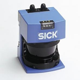
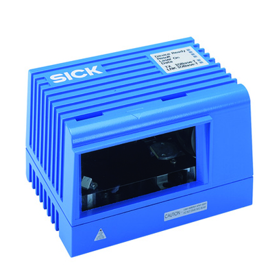
Both the SICK PLS 101 (left), which is used in the mild platform, as well as the SICK LMS 400 (right), which has been used for evaluation of the calibration tool, have been integrated into the package and can be selected by changing a single parameter (laserscanner_type).
While the PLS 101 scanner operates on infrared light, the LMS 400 laserscanner uses visible light wave ranges, which makes evaluating the calibration data much easier.
The supported types of PTU units depend on the asr_flir_ptu_driver package and are described there.
All cameras supported by the asr_resources_for_vision package can be used for calibration.
Start system
To launch the calibration tool, use
roslaunch asr_mild_calibration_tool calibration_tool.launch
ROS Nodes
Subscribed Topics
/scan
publisher: asr_sick_lms_400 (LMS 400) / asr_mild_base_laserscanner (PLS 101)
- contains the laserscan range scans
/stereo/objects
publisher: asr_aruco_marker_recognition
- contains information about recognized markers
<tf_visualizer_camera_input_topic>
publisher: asr_resources_for_vision
topic name has to be set in parameter file!
- contains the current camera image
Published Topics
/calibrationObject/Object
- message type: /visualization_msgs/Marker
- description: publishes the recognized calibration object
/calibrationObject/Marker
- message type: /visualization_msgs/Marker
- description: publishes the calibration markers relative to the recognized calibration object
/calibrationObject/Camera
- message type: /visualization_msgs/Marker
- description: publishes the camera pose relative to the calibration marker
/average_scan_data
- message type: /sensor_msgs/LaserScan
- description: A set of Laserscan ranges averaged over the last 100 values
/segment_border_scan_data
- message type: /visualization_msgs/MarkerArray
- description: A set of Laserscan ranges colored either black (border area) or white (inner area) depending on how far the points are to an outer edge of a segment.
/segmented_scan_data
- message type: /visualization_msgs/MarkerArray
- description: A set of Laserscan ranges colored according to which segment each point belongs to.
<tf_visualizer_camera_output_topic>
- message type: /sensor_msgs/Image
description: camera image overlayed with the frames specified in the tf_visualizer_frames parameter
Published Frames
During calibration, several frames containing frames used in the calibration process are being published:
calibration_transforms
- object_top
- Frame at the top of the calibration object's tetrahedon
- object_base
- Frame at the base of the calibration object's tetrahedon
- calibration_center
- The laserscanners sensor origin frame
- object_scan_frame
- Frame at the intersection of the calibration object with laserscanner's sensor plane
- marker_left
- Lower right corner of the calibration object's left marker
- marker_right
- Lower left corner of the calibration object's right marker
- camera_frame
- Pose of the camera system relative to the calibration object's markers
- camera_left_frame
- Pose of the left camera according to the robot's kinematic chain
- camera_right_frame
- Pose of the right camera according to the robot's kinematic chain
- object_top
Parameters
Calibration tool settings
The general settings for the mild calibration tool are specified in the calibration_tool_settings.yaml file. The following parameters are available:
Laserscanner detection: This set of parameters are required for the detection of the calibration object with the robot's laserscanner.
laserscanner_maxVariance: Used for the max-variance-filter in the edge detection. When trying to detect a side of the calibration object with the laserscanner, this value specifies the maximum variance among a set of measured range points to be still considered as a candidate for a side of the calibration object.
laserscanner_maxAngleDeviation: Used for the angle filter in the edge detection. Once two candidates for the left and the right side of the calibration object have been found, their angle towards each other should be approximately 90°. This value specifies the maximum deviation from a right angle for those two measured sides to be still considered a valid edge.
feasibilityChecker_maxAngleDeviation: When calculating the pose of a detected calibration object, the system can (in the context of the mild platform) usually expect the object to stand approximately to parallel to the laserscanner's sensor plane. Therefore, calculation results with poses that deviate too much from this orientation can be discarded. This parameter specifies the maximum allowed angle deviation relative to laserscanner's sensor plane in order to be considered a valid result.
laserscanner_variationStep: When trying to find the exact center for calibration object's edge, for each candidate point, a set of sampling points aligned in a regular grid around it are considered as candidates as well. The distance between two neighbouring points in this grid is described by this value.
laserscanner_variationStepCount: Used for the generation of the grid described above. This parameters describes the number of rows and columns of the sampling grid.
laserscanner_segmentation_lambda: During edge detection, the measured distance points are segmented first. This parameter specifies the maximum distance between two consecutive points, to be still considered part of the same segment.
laserscanner_type: For detecting the calibration object, two laserscanners can be selected. Options are the LMS400 or the PLS101 (see "Needed Hardware" for more information)
Camera marker detection: This set of parameters are required to detected the calibration object (more precisely, the AR-markers attached to it) via the robot's cameras.
tilt_min_angle: Mininum angle of the tilt joint during the automatic marker search
tilt_max_angle: Maximum angle of the tilt joint during the automatic marker search
pan_min_angle: Mininum angle of the pan joint during the automatic marker search
pan_max_angle: Maximum angle of the pan joint during the automatic marker search
tilt_step_count: Number of steps to iterate from the mininum angle to the maximum angle of the tilt joint during the automatic marker search
pan_step_count: Number of steps to iterate from the mininum angle to the maximum angle of the pan joint during the automatic marker search
marker_recognizer_timeout: Time (in seconds) to wait for data from the marker recognizer in each iteration step of the automatic marker search
marker_recognizer_early_abort_timeout: Time (in seconds) to wait for the first set of data from the marker recognizer in each iteration step of the automatic marker search. If no data arrives before during this period, the marker search will automatically advance to the next iteration step.
marker_min_distance: Minimum distance between a detected marker pose and the camera to be considered a valid pose. Used to detect outliers.
marker_max_distance: Maximum distance between a detected marker pose and the camera to be considered a valid pose. Used to detect outliers.
useAveragedMarkerData: If true, the measured poses of marker during each iteration of the automatic marker search are being averaged using SLERP Only the average value will be saved for each iteration step.
Visualization: The following parameters are need to generate an overlay over the camera image, visualizing a set of tf frames over the camera's image
tf_visualizer_camera_input_topic: Name of the topic, to which the original camera image is published
tf_visualizer_camera_output_topic: Name of the topic, to which the overlayed image will be published
tf_visualizer_frames: Name of frames, that should be visualized
Needed Services
- /asr_aruco_marker_recognition/get_recognizer :
- Starts recognition of a marker
- /asr_aruco_marker_recognition/release_recognizer :
- Stops recognition of a marker


