Package Summary
This package is a ROS wrapper that set up the communication and control of the ZLP1 Z-LASER Projector, making it fully compatible with all available sensors and devices running over the ROS-Industrial project. For that purpose, it provides a ROS API that expose the different functionalities offered by the device.
- Maintainer status: maintained
- Maintainer: Rafael Luque <rluque AT catec DOT aero>, Ines M. Lara <imlara AT catec DOT aero>
- Author: Rafael Luque <rluque AT catec DOT aero>, Ines M. Lara <imlara AT catec DOT aero>
- License: Apache 2.0
- Source: git https://github.com/fada-catec/z_laser_projector.git (branch: melodic)
Package Summary
This package is a ROS wrapper that set up the communication and control of the ZLP1 Z-LASER Projector, making it fully compatible with all available sensors and devices running over the ROS-Industrial project. For that purpose, it provides a ROS API that expose the different functionalities offered by the device.
- Maintainer status: maintained
- Maintainer: Rafael Luque <rluque AT catec DOT aero>, Ines M. Lara <imlara AT catec DOT aero>
- Author: Rafael Luque <rluque AT catec DOT aero>, Ines M. Lara <imlara AT catec DOT aero>
- License: Apache 2.0
- Source: git https://github.com/fada-catec/z_laser_projector.git (branch: noetic)
Contents
Overview
Software architecture
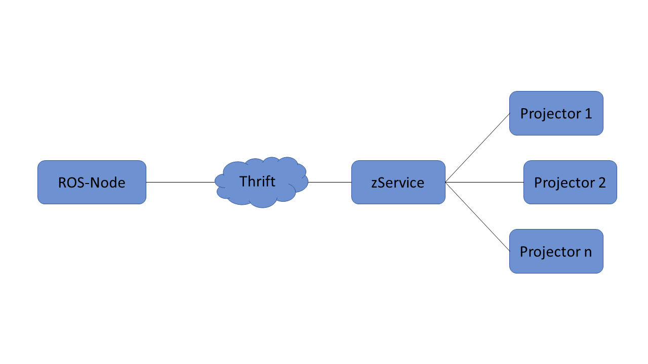
The ZLP software has a modular architecture. These modules communicate via TCP/IP and have to be located within the same network.
Z-Laser offers different solutions depending on where you prefer to have zService running. This package has been developed in a device with zService built-in to the projector itself.
In this case, zService IP address is 192.168.10.11, on port 9090. In case you have zService running on your PC, contact z-laser to get the specific IP address of your device.
Projector is expected to be reachable under 192.168.10.10 (factory default configuration).
To get more information about Thrift and zService, refer to ZLP1-quickstart-guide (provided by z-laser).
Reference coordinate systems
The laser projector ZLP1 covers working fields from 1.0m x 1.0m up to 3.5m x 3.5m; and working distances from 1.0m to 3.0m. It is able to project figures in a specific position at various workpiece distances. It also has the ability to move and rotate the displayed object. To do this, you need to specify a reference coordinate system first. In order to embrace this issue, the definition and setting up of reference coordinate systems will be further explained in this section.
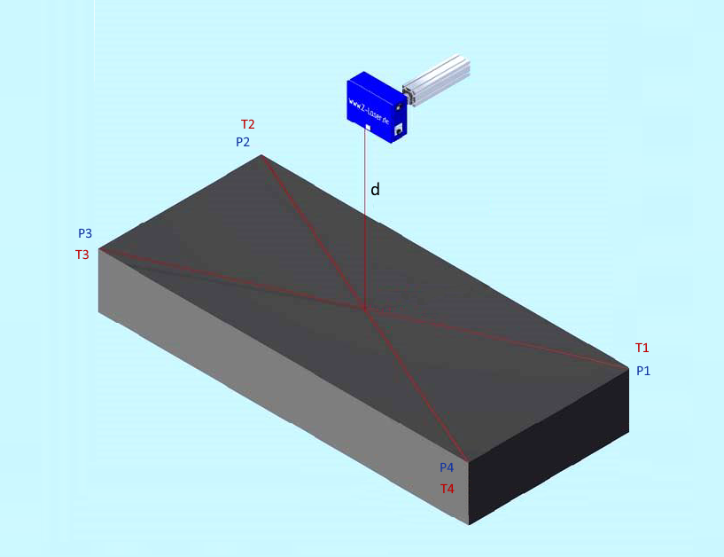
There are two ways to specify a coordinate system: either by setting the coordinates manually, or by automatic target search. Note that each point on the projection surface can be referenced by two different coordinate systems:
- Projector Reference System {P}. Specified in factory, the coordinate system origin is always the same and cannot be changed. User-defined reference systems have to be related to this.
- User Reference System {T}. The user can set the coordinate system origin, its resolution and orientation. It must be related to {P}.
Note that a coordinate system needs 4 points to be fully defined.
Setting user-defined reference system manually
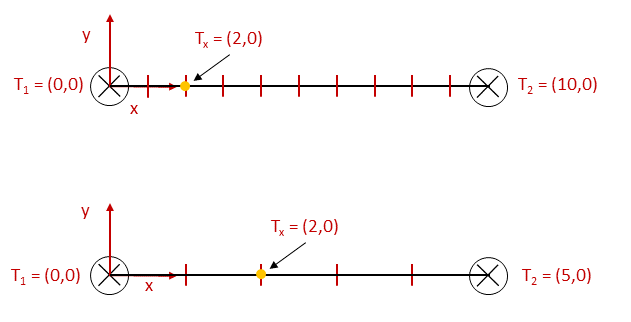
An example of manual system definition is going to be developed in order to guide this section. First, the user must decide the coordinate system’s resolution to set a position. See the differences in the scheme below. This value is non-dimensional, i.e., do not represent real world dimensions.
For the following example, we use a resolution of 1000. Then, the user should indicate the position of the four points that define the coordinate system in real world values (millimetres). This means to specify the desired correspondent points in Projector Reference System {P}. For example:
P0 = (-100, -100) [mm]
P1 = (-100, 100) [mm]
P2 = (100, 100) [mm]
P3 = (100, -100) [mm]
Please, be careful to indicate dimensions that correspond to either a square or a rectangle.
Finally, the user is required to introduce the value for T0 that will form the User Reference System {T}. Then, the following points will be auto-defined based on the resolution value. In case the above values represent a square as in the example, resolution is applied directly:
T0 = (0, 0)
T1 = (1000, 0)
T2 = (0, 1000)
T3 = (1000, 1000)
However, if it is a rectangle, resolution is applied to axis with the longest dimension and autoscaled for the other. When creating a coordinate system, those values are returned for the user to know.
This is a scheme of the example:
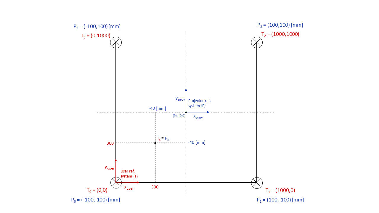
In the image above, the point Tx = (300, 300) referenced from User Reference System {T}, will be located on the real projection surface at Px = (-40mm, -40mm) from the origin of Projector Reference System {P}.
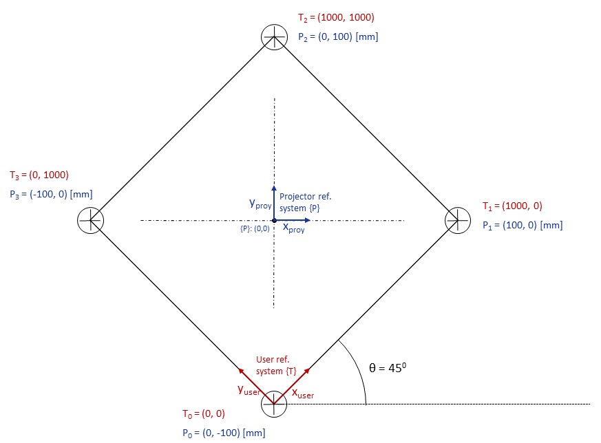
On the other hand, some situations may require a rotation of the reference system. To achieve that, the user should set the appropriate coordinates in Projector Reference System {P}. In the scheme below, note that User Reference System {T} remains the same with respect to the previous example, while Projector Reference System {P} changed to:
P0 = (0, -100) [mm]
P1 = (100, 0) [mm]
P2 = (0, 100) [mm]
P3 = (-100, 0) [mm]
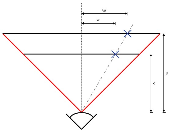
Finally, notice that real world coordinates specified in Projector Reference System {P} depends on the projection distance (distance between the laser projector and the projection surface), as it is a beam.
In this example, the real distance between projector and surface is ‘d’. If it is incorrectly indicated as a greater distance ‘D’, the projected points would be located more distant (‘W’) to the coordinate system origin than the user has specified (‘w’).
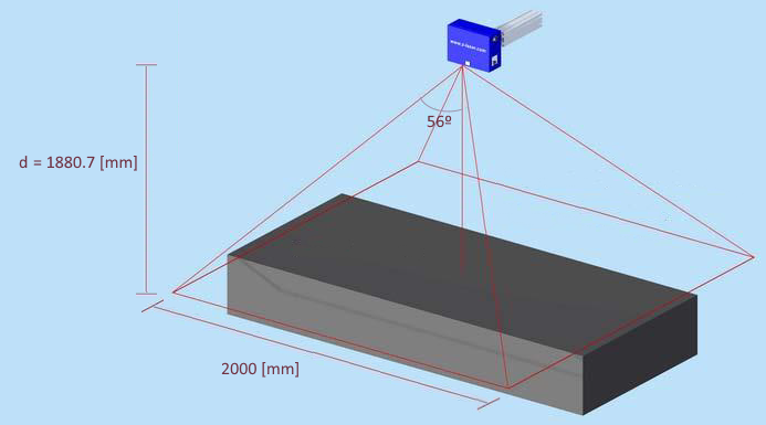
For that reason, the installation projection distance must be correctly indicated, and it can be calculated using the following formula: d = f * 0.5 / (tan(α/2)) where
- d: is the projection distance in [mm]
- f: longest side of the projection surface in [mm]
- α: optical opening angle of value 56º.
For example:
Given a length of the desired projection area of 2000mm and an opening angle of 56o, it results in an installation distance of 1880.7mm:
Setting user-defined reference system by targets scan
The procedure is similar to the manual definition but in this case, the user indicates the approximate position of the targets that correspond to the P0, P1, P2 and P3 points. After that, the projector device scans these approximate positions and redefines the reference system with the exact ones.
ROS API
The zlp_projector_zlp1 provides a collection of topics, services and parameters in order to operate the projector device from ROS environment, as connecting, disconnecting, defining coordinate systems, starting and stopping projection, etc.
Topics
~add_projection_element (z_laser_msgs/Figure)
- Define a new figure as projection element linked to the active reference system. Nevertheless, it will not be visible until the projection is triggered
- Define a new scannable pointer as projection element linked to the active reference system
Services
~connect (std_srvs/Trigger)
- Open connection with projector
- Close connection with projector
- Start projection of elements linked to the active reference system on the surface
- Stop projection of all elements
- Define a new reference system with the points coordinates given manually by the user
- Define a new reference system by scanning the position of the targets (reflectors). The user has to provide the approximate position of these points
- Get the list of defined reference systems
- Set the reference system indicated as active. The other systems remain in the background
- Remove the active reference system. Then, you must set another
- Project reference points, origin axes and frame of the active reference system for n seconds
- Hide projection element from the active reference system
- Unhide projection element from the active reference system
- Remove projection element from the active reference system
- Monitor projection element with the keyboard
- Start pointer scanning
Parameters
~projector_IP (string)
- Projector IP address
- ZLP-Server IP address
- Connection port number
- ZLP license file path
- Name of reference system
- Resolution of reference system
- Distance between laser projector device and projection surface
- x-position of point P0, P1, P2 or P3 from projector reference system {P}
- y-position of point P0, P1, P2 or P3 from projector reference system {P}
- x-position of point T0 from user reference system {T}
- y-position of point T0 from user reference system {T}
- Connection status of the device
- Indicates if running visualizer
Acknowledgement

Supported by ROSIN - ROS-Industrial Quality-Assured Robot Software Components.
More information: rosin-project.eu
|
This project has received funding from the European Union’s Horizon 2020 |


