atopile brings the best of software development to the world of hardware design.
We're starting with an electronics compiler and a new language called ato. Files with the .ato extension can be used to describe your circuit, and compiles it to netlists that can be laid out and fabricated.
The .ato files are human readable and can be version controlled, so you can collaborate with your team on the design of your hardware. They're modular, so you can reuse components from other projects, and share them with the community. They provide a way to save the intelligence of your design and the validation required to make sure it works as intended, so you can be confident that your design will work as expected.
To get started, you can invoke the ato create 'path/to/your project's name command. This will clone the template project in your local directory and create a remote directory in atopile's gitlab instance.
You can find inspiration in a more advanced project like the servo-drive: https://gitlab.atopile.io/atopile/servo-drive
- Developer installation -> REAMDE.md
There's two basic routes to installing atopile; either you're familiar with python, sysadminy stuff and the command line, and you'd like to use it -- or you're not.
- Install VSCode
- Install the dev containers extension
- Clone your template repo
- Open it in VSCode

Click the "Show Log" at the top of this modal

Wait a sec for the container's image to download and the container to start

- Requires:
python3.11or laterpipgit- perhaps manually installing some deps we've forked
The root of an ato project is marked by the presence of an ato.yaml file.
ato.yaml contains some project configuration information like the list of things you want to build. It's similar in concept to a package.json in js/node/npm land.
Here's an example:
# this line defines the version of compiler required to compile the project
ato-version: ^0.0.18
# those line defines the path where the build artifact will be placed by the compiler
paths:
  build: ../../build/
# those lines define the elements that will be built by the compiler
builds:
  default:
    # we don't have a default root file yet
    targets:
      - netlist-kicad6
      - designators
      - bom-jlcpcb
The compiler version follows sementic versioning. The required version to compile your project can be specified using npm's standard.
Components and footprints can be added manually to your project. For convenience, you can also use the ato install command. Here is an example installing the (RP2040 chip)[https://www.lcsc.com/product-detail/Microcontroller-Units-MCUs-MPUs-SOCs_Raspberry-Pi-RP2040_C2040.html]:
ato install --jlcpcb 'C2040'
The command will add your footprint and 3D representation to the KiCAD library (named lib in your folder structure) and create an ato file of the component.
You can import assets by specifying what you want to import and where you want to import it from using the following syntax:
import What from "where.ato"
Notes on that statement:
- add quotes on the "where.ato" - it's a string
Whatis capitalised - it's a type and types should be capitalised, though this isn't enforced and you can import things other than types from other files
The import statements are with respect to the current project, or within the standard library (std)
There's a handful of major types that you'll use in your .ato files, falling into two categories; blocks and nodes.
Blocks represent something that can contain other things. They provide an abstration over their contents. For example, a block could be power supply chip and all the passive components around it.
Nodes are elements you can connect to.
Block types are:
component- represents exactly one componentmodule- a collection of components and other modulesinterface- walks the line between a block and a node. It's a connectable block that let's you connect multiple nodes at a time
Node types are:
pin- represents a physical pin/pad on a packagesignal- represents a logical signal that can be connected to other signals
Here is an example of a block (in this case a component) created within a file named led.ato:
component LED:
    signal positive  # declare a signal named "positive"
    positive ~ pin 1  # connect that "positive" signal with pin 1
    signal negative ~ pin 2  # declare a signal named "negative" and connect it with pin 2 in one line
    footprint = "Resistor_SMD:R_0603_1608Metric"  # yeah, I know this is a resistor package, but bare with me
ato view is still in development. Please expect the feature to be unstable.
ato view --help will give you a printout of the options it can take.
atopile paths are in the form path/to/file.ato:module.within.file
To view, the LED component for example: ato view led.ato:LED
You should get a browser window popping up and wham! bam! alakazam! you've got a component!
JLCPCB is a great place to get cheap PCBs made. They have a library of footprints that you can use.
To pull in a footprint, we've been using the wonderful tool easyeda2kicad.
Add it to your python environment with pip install easyeda2kicad
Then you can download JLCPCB/EasyEDA/LCSC footprints with easyeda2kicad --full --lcsc_id=<LCSC-num> --output ../lib/lib
ato build is the tool for you!
For example: ato build --target=netlist-kicad6 led.ato:LED
This will generate a netlist in the build/default directory.
You can build any supported target with this same command just by changing the value of the --target option.
While creating a new project and where to place your KiCAD files is out of scope of this tutorial, if you simply need to reimport a netlist into KiCAD, you can do the following:
- File -> Import Netlist
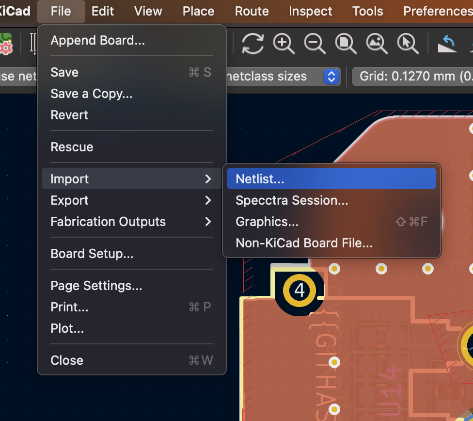
- Select the netlist you've just generated. The output is in the terminal, but it should approximately be servo-drive/build/servo-drive.net
- Make sure you're using unique IDs, rather than designators (though they should work too)
- Ruthlessly destroy stuff that's not supposed to be there (check boxes on the right)
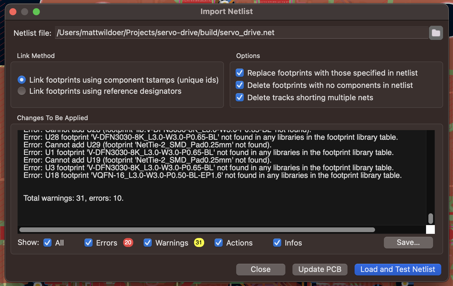
- Check the errors - sometimes it's important


In case you want to setup your own project, we have prepared a template with sample ato code and KiCAD project. Find it here.
Like classes in most modern languages, we can subclass and inherit from blocks.
module SomeModule:
    signal some_signal
    signal gnd
    some_variable = "some value"

module SubclassedModule from SomeModule:
    # inherits all the signals and variables from SomeModule
    # we don't need to declare the signals again, but we will replace the value of some_variable
    some_variable = "some other value"

module Test:
    signal gnd
    subclased_module = new SubclassedModule  # creates an instance of the SubclassedModule
    subclased_module.gnd ~ gnd  # connects the some_signal of the SubclassedModule to the gnd of Test
note: we can subclass a module as a component, but not the other way around. A component is expected to represent a specific component.
This subclassing is also useful for creating typed interfaces:
interface I2C:
    signal sda
    signal scl

module SomeModule:
    i2c = new I2C

module Test:
    a = new SomeModule
    b = new SomeModule
    a.i2c ~ b.i2c  # connects both sda and scl in one fell swoop
This operator allows you to increase the specificity of a block somewhere.
Take the following example:
- You want to create a reusable half-bridge module
- If you spec the FETs within the module, you can't readily reuse the design in other projects with other FETs
- If you don't declare the FETs at the bottom level it's a PITA to use, since every time you use it you need to remember to slot the FET in the right spot
You want some way to say "we're putting a FET here, but we'll tell you which FET later"
Subclassing is the way you say what a FET is, the replacement operator gives you the later.
module NFET:
    signal gate
    signal source
    signal drain

module HalfBridge:
    signal high
    signal low
    signal output
    signal high_gate
    signal low_gate

    high_fet = new NFET
    low_fet = new NFET

    # let's pretend we do something useful here like hook it all up

# some time later... perhaps in another file

component SomeNFET from NFET:
    footprint = "TO-220-3_Vertical"  # this isn't a legit package, but you get the idea

module MotorController:
    a = new HalfBridge
    # ...
    # replace the fets with a SomeNFET
    a.high_fet -> SomeNFET
    a.low_fet -> SomeNFET
git fetch origin git pull
git checkout -b <branch-name>
git checkout -b <branch-name> <from-branch>
eg. git checkout -b mawildoer/new-feature origin/main
git add <whatever-you-wanna-save>
git add . -- save everything I've changed (including perhaps things we forgot to .gitignore)
git commit
git commit -m "<message-here>"
git push works if you didn't spec a "from" branch in git checkout -b ...
git push -u origin HEAD always works
Will respond with a way to make a branch:
remote:
remote: To create a merge request for mawildoer/dummy-branch, visit:
remote:   https://gitlab.atopile.io/atopile/servo-drive/-/merge_requests/new?merge_request%5Bsource_branch%5D=mawildoer%2Fdummy-branch
remote:
To gitlab.atopile.io:atopile/servo-drive.git
Cmd+ on the link to gitlab
Our CI pipeline will automatically generate the following outputs for you:
- Gerbers (with githash automatically stamped on it!)
- BOM
- Pick and place file
To download the artifacts, go to the pipeline page and click on the download button:

download the "store-build:archive" artifact and extract, you should see soemthing like this:

===
The atopile language is largely (at least syntactically) based on python.
If you're wondering how to write good ato code, considering what something might
look like in python is a good start. We also recommend checking out their
style guide (pep8) for a reference on styling.
There are pretty obviously vast differences in how ato and python work though, so while it may make a good start, we do not plan to re-implement all of python's features...
... we've got our own!
Remember how NASA slung a rocket straight into Mars because of a metric/imperial boo boo?
How about we don't do that again.
Resistors's resistances must be a resistance; whether 1.23Ω (option+Z on OSx), 1.23ohm, 4.56Kohm, 7.89Mohm or similar.
Any attribute of any block may have a unit attached written (without a space) after any number.
Unsurprisingly, caps capacitances need to be a capacitance; eg. 23.4uF, various limits in volts, amperes, degrees and so on.
Add units.
Another unfamiliar first-class language feature when dealing with the physical world is the ability (and generally requirement) to spec tolerances for attributes.
You could try find a 10kΩ resistor, but my money says you won't - it'll likely be at least 10kΩ +/- 0.1% (which you can
write!)
Tolerances can be written in the forms of:
1V to 2V3uF +/- 1uF4Kohm +/- 1%
These are hopefully sufficiently intuitive as to not warrant further explanation 🤞
With Units and Tolerances together, we can define Physical attributes.
There's quite a few legal ways to combine them!
3V to 3.6Vperhaps for a supply rail3V +/- 10mVmaybe for a reference4.7uF +/- 20%for a generic cap- even
25lb +/- 200g🤣
Doc-strings should be used to add in-code documentation of modules.
eg.
module MyModule:
    """
    This is a hiiiiigh quality module!
    """
This documentation not only helps you remember what you did, but also means your package is searchable and useable by others.
Versions within atopile follow the semantic versioning 2.x schema. See https://semver.org for details
Semantic versions may be prefixed with a "v", so v1.0.0 == 1.0.0
The ato.yaml is significant indicator for a project:
- It marks the root of a project. The
atocommands in the CLI is largely dependant upon theato.yamlto know what project you're referring to. - It contains project-level configuration information like where to build from, which layouts have what entry-points
- Lists project dependencies and the required versions of those dependencies
- Specifies what compiler version the project is intended to build with
Each package listed under the dependencies: key is automatically downloaded and installed for users when they run the ato install
command from within a project. These dependencies are anticipated to make the project run.
Each dependency may have constraints on its version using the following operators:
Assuming dependency says my-package <operator>1.2.3 the following table describes whether each of the operators would match.
They're in approximate order of usefulness/recommendation
| Op | 0.1.1 |
1.1.0 |
1.2.3 |
1.2.4 |
1.3.0 |
1.4.0 |
2.0.0 |
Description |
|---|---|---|---|---|---|---|---|---|
^ |
✔ | ✔ | ✔ | ✔ | >=, up to the next major | |||
~ |
✔ | ✔ | >=, up to the next minor | |||||
== |
✔ | Exactly | ||||||
* |
✔ | ✔ | ✔ | ✔ | ✔ | ✔ | ✔ | Any |
! |
✔ | ✔ | ✔ | ✔ | ✔ | ✔ | Not (usually used in combination with others) |
>=, <=, >, < all work, but have niche value. If you need to use them, something's probably broken.
eg. ato-version: v0.1.8
The installed compiler is matched against this value to see if the project is buildable in the current environment.
It's matched using either:
~if the installed compiler version<1.0.0- else
^(up to the next major)
Practically, this means breaking compiler changes are indicated using the minor (eg. 0.1.0, 0.2.0, 0.3.0, 0.4.0) until version 1.0.0.
When you upgrade your compiler with breaking changes, you need to update your project to match the language changes, bumping this version in your project's ato.yaml file