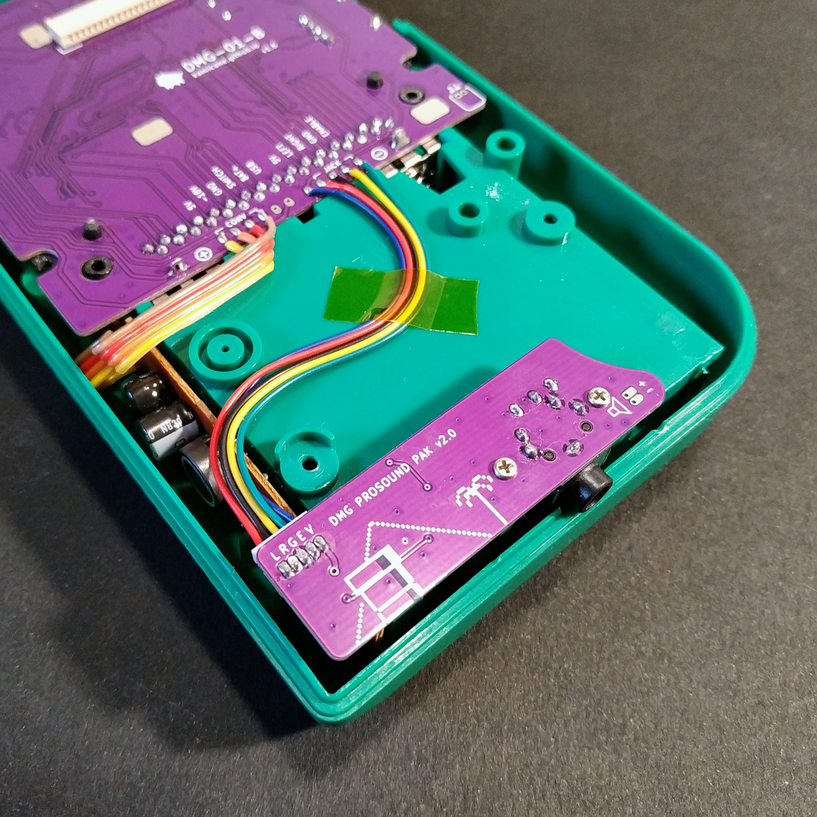
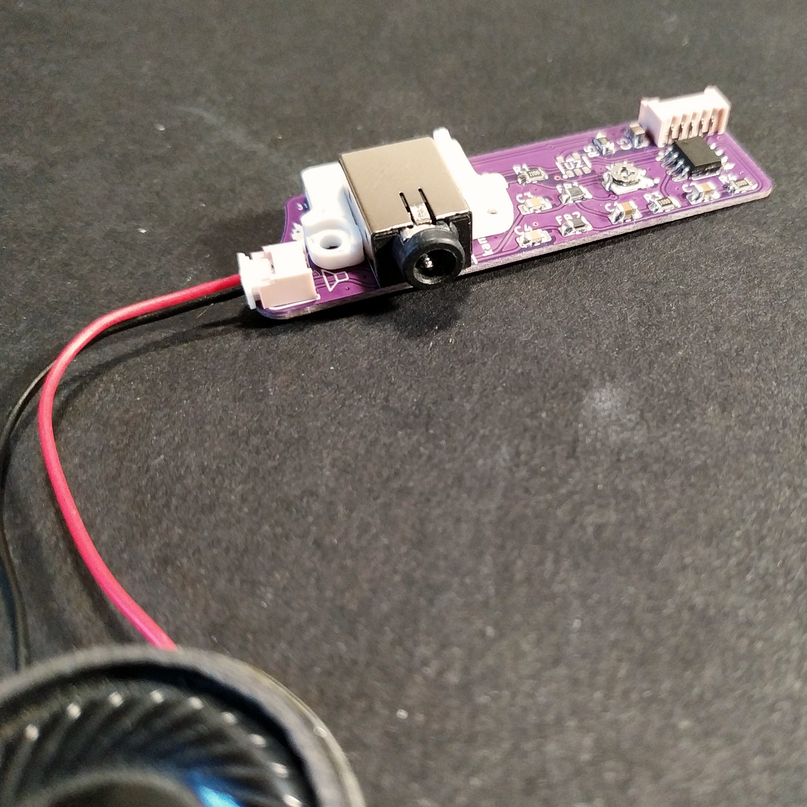
Super DMG JACK is a replacement headphone/audio PCB for the original Game Boy. It can be used on a stock DMG or the Super DMG-01.
It uses a PAM8302 mono amplifier to power the speaker when no headphones are present, but it can also be built as a headphone jack replacement using the amplifier on the CPU board.
The amplifier schematic is based on Adafruit's pam8302 amplifier PCB.
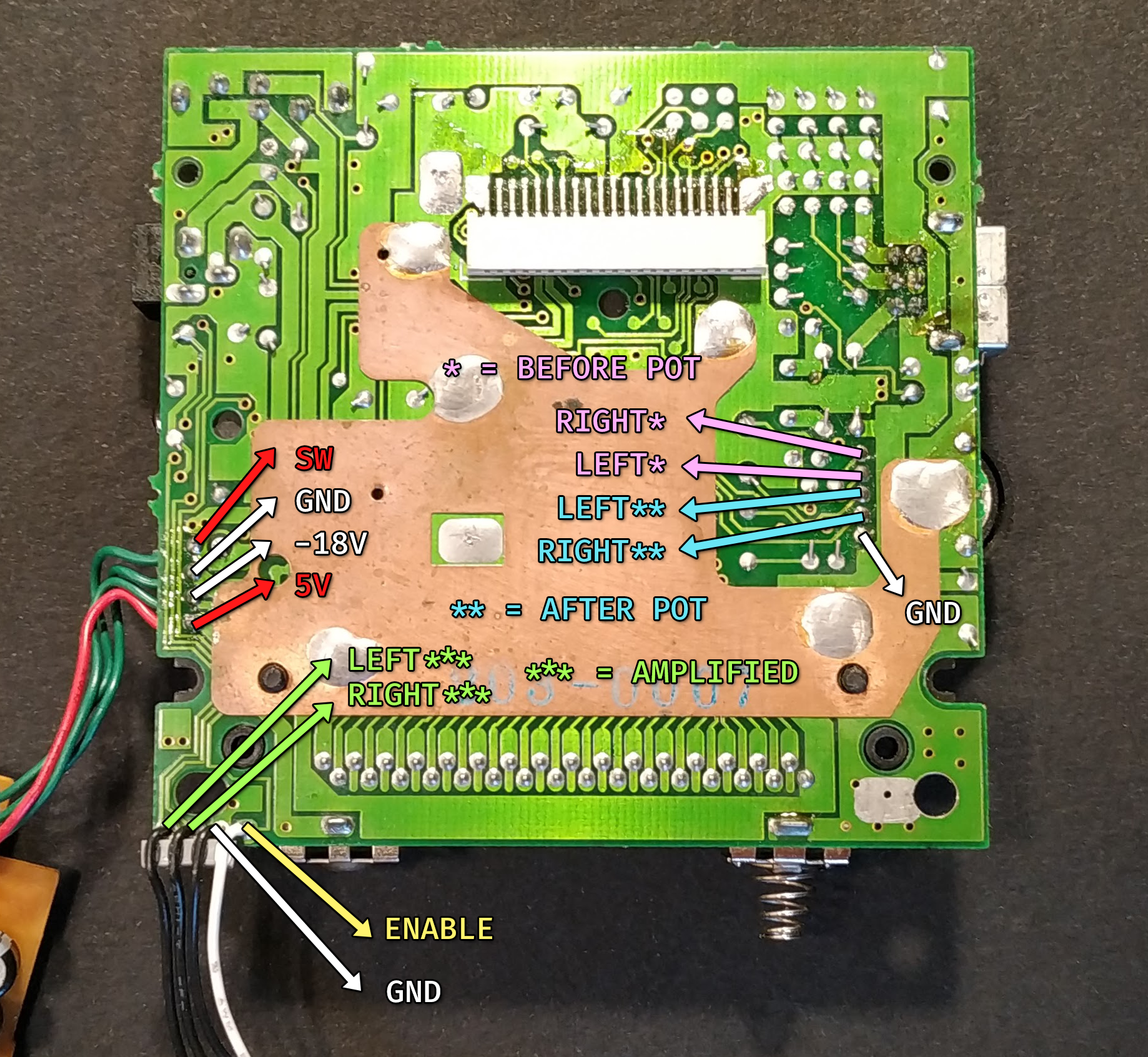
The headphone output needs to be unamplified, and grabbed after the DMG volume potentiometer.
| Designator | Package | Qty | Value / Description | Source |
|---|---|---|---|---|
| CN1 | PJ-3043-B | 1 | Headphone connector | LCSC |
| CN2 | 1.25 TH | 1 | CPU PCB Connector | LCSC |
| CN3 | 1.25 TH | 1 | Speaker Connector | LCSC |
| U1 | SOP-8 | 1 | PAM8302 | LCSC |
| U2 | SOT-23-5 | 1 | SN74AHC1G14 | LCSC |
| VR1 | Bourns TC33X-2-103E | 1 | 10kΩ SMD | LCSC |
| FB1, FB2 | 0805 | 2 | Ferrite Bead | |
| C1, C2, C5 | 0805 | 3 | 1µf | |
| C3, C4 | 0805 | 3 | 220pf | |
| R1, R2 | 0805 | 2 | 220Ω | |
| R3, R4 | 0805 | 2 | 100Ω | |
| R5 | 0805 | 1 | 10kΩ |
I got premade wires from AliExpress (1.25mm 2p and 5p), but you can also just use 28/30 awg without connectors.
I use "WSC" 8Ω 2W speakers from AliExpress.
Important: do not solder U2 and/or do not wire the (E)nable signal. The speaker must be connected to this board.
- Solder the SMD components
- Solder the through hole components
- On the stock DMG solder the L/R signals to the volume potentiometer (** after pot), on Super DMG-01 solder to the bottom pads directly
- Get power from the 5v rail on the CPU board
- Adjust the trimpot
Adjust the trimpot to reduce the power draw and max volume of the amplifier. Boot the DMG at minimum volume, and slowly turn it up, while also adjusting the trimpot. The Game Boy will shut down if you're drawing too much power. Do the final trimpot adjustment once the DMG volume is at its maximum value.
The final maximum volume will depend on the batteries and the voltage regulator you're using.
The jack-only installation is meant to be used with the on-board DMG amplifier, however you still need to solder an extra wire for power as the ENABLE signal needs to be inverted.
Important: solder only U2, R5, the headphone jack and the CPU PCB connector. The speaker must be kept in the LCD board.
- Solder the SMD components
- Solder the through hole components
- On the stock DMG solder the L/R signals to the volume potentiometer (** after pot), on Super DMG-01 solder to the bottom pads directly
- Get power from 5V (Super DMG CPU) or SW (stock DMG) on the CPU board
3d print the jack spacer for correct alignment.
Make sure you order in 1.0mm thickness.
This work is licensed under the Creative Commons Attribution-ShareAlike 4.0 International License.


