Skip to content
New issue

Have a question about this project? Sign up for a free GitHub account to open an issue and contact its maintainers and the community.

By clicking “Sign up for GitHub”, you agree to our terms of service and privacy statement. We’ll occasionally send you account related emails.

Already on GitHub? Sign in to your account

LCD Dot matrix with Toshiba T7932 and T7933 / HD44102 #1492

Closed
ObligedTester opened this issue May 12, 2021 · 23 comments
Closed

LCD Dot matrix with Toshiba T7932 and T7933 / HD44102 #1492

ObligedTester opened this issue May 12, 2021 · 23 comments
Milestone

Comments

@ObligedTester
Copy link

ObligedTester commented May 12, 2021

Hi!

I have this really nice LCD module that i pulled out of a old POS-terminal.
Could not find much on that particular module, however the controller consists of 3x T7932 chips, and one T7933 chip.
I take a shot in the dark and hope that this may be some "standard" already compatible with another driver?

What do you think? Datasheets: https://www.alldatasheet.com/datasheet-pdf/pdf/31153/TOSHIBA/T7932.html & https://pdf1.alldatasheet.com/datasheet-pdf/view/31154/TOSHIBA/T7933.html

Also, if you have a teory that it might be compatible with some other library, i will be happy to test it out

@ObligedTester
Copy link
Author

Hello again,

I found this: https://forum.arduino.cc/t/openglcd-hd44102-to-t7932/413755
So it seems that would be a good starting point, does U8g2 have a driver for HD44102 or equivalent?

@olikraus
Copy link
Owner

Hmmm... never heard about hd44102 LCD. It is not supported :-(

@olikraus
Copy link
Owner

I will try to buy and add support for such a display with HD44102, but it might take 2-3 months (such displays are not easy to get...)

@ObligedTester
Copy link
Author

That's great!
However, this week i will receive a FPC adapter for my module T7932/T7933.
I'm no LCD-expert, but with a little assistance I will be more than happy to try and help out.
Do you have any hunch on if there is a "base" module that might be good to use that is in the library right now when looking at the datasheet?

@olikraus
Copy link
Owner

Maybe the ks0108 could be a starting point.

@ObligedTester
Copy link
Author

Thank you!

Will give that a shot when I get my adapter and report back!

@olikraus olikraus changed the title LCD Dot matrix with Toshiba T7932 and T7933 LCD Dot matrix with Toshiba T7932 and T7933 / HD44102 Jun 15, 2021
@olikraus olikraus added this to the 2.29 milestone Jun 15, 2021
@olikraus
Copy link
Owner

olikraus commented Jun 15, 2021

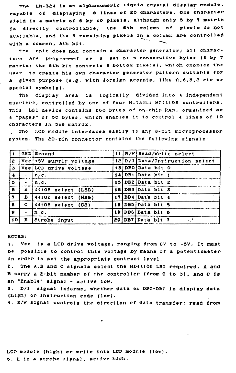
Some progress here. I might get a LM324 display with the HD44102 controller.

lm324_hd44102_2

@ObligedTester
Copy link
Author

Hi Oli!
Thank you very much for this update.
In the last days I have received my FPC-adapterboard, that will make it possible to hook everything up to a breadboard without modifying anything. I will be happy to help with any sort of debugging that might be needed. Just let me know.

Will be documenting the pinout for this LCD also to aid anyone else that might stumble on them. They are very nice

@olikraus
Copy link
Owner

Great. It will probably take some more days until I receive the display itself.

@olikraus
Copy link
Owner

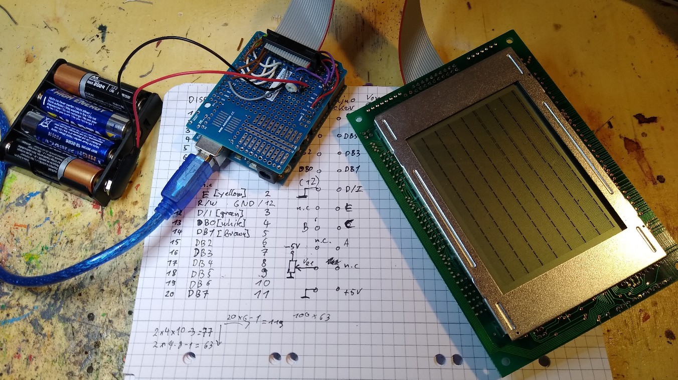
I recently got access to the display. After wiring with my Arduino it seems to work. U8g2 software development not yet started, I just wanted to see whether the adapter board works.

IMG_20210725_203344588

olikraus added a commit that referenced this issue Jul 25, 2021
@ObligedTester
Copy link
Author

ObligedTester commented Jul 29, 2021

Hello,

Thank you for your update! This is exciting

I have just traced my pinout for mine. Think i have them all, though, i have also 3 NCs, seem to valid with your data sheet also. These is the signal pins i was able to find:

VDD
VSS
E (/WR)
R/W (/RD)
D/I (Not sure how that one is handled)
DB0-7
CS 1-3
RST

Seems like the backlight on this one is permanently hooked to the supply.

Do you have any baseplate code that might give me some initial life from this one?

@olikraus
Copy link
Owner

olikraus commented Jul 30, 2021

This is the connection table for my current test setup. "D/I" is important and will be controlled by u8g2. Same is true for "E". "R/W" must be connected to GND permanently because U8g2 will only write but never read from the display (However for testing, I have connected this to pin 12 in my test setup). "Vee" must be a negative voltage (around -4..-5V). I have just used 4x AA cells to generate the negative voltage. My display does not require a reset pin (RST), but u8g2 can handle the reset functionality. In your case: VSS = GND, VDD = +5V (probably, check your datasheet for this).
Of course your display might have different pin numbers and also the Arduino pins can be changed (Arduino pins are provided to the U8g2 Constructor).

Disp. Pin Disp. Fn. Arduino Pin Wire Color U8g2 Constructor Arg
1 GND GND black -
2 +5V +5V red -
3 Vee (10K VarPot) - - -
4 n.c. - - -
5 n.c. - - -
6 A (chip select) A0 purple cs0
7 B (chip select) A1 purple cs1
8 C (chip select) A2 purple cs2
9 n.c. - - -
10 E (write pulse) 2 yellow enable
11 R/W (read/write mode) GND (12) - grey
12 D/I (data/cmd mode) 3 green dc
13 DB0 4 white d0
14 DB1 5 brown d1
15 DB2 6 white d2
16 DB3 7 brown d3
17 DB4 8 white d4
18 DB5 9 brown d5
19 DB6 10 white d6
20 DB7 11 brown d7

The constructor will probably look like this:

U8G2_HD44102_100X64_1(const u8g2_cb_t *rotation, uint8_t d0, uint8_t d1, uint8_t d2, uint8_t d3, uint8_t d4, uint8_t d5, uint8_t d6, uint8_t d7, uint8_t enable, uint8_t dc, uint8_t cs0, uint8_t cs1, uint8_t cs2, uint8_t reset = U8X8_PIN_NONE)
U8G2_T7932_150X32_1(const u8g2_cb_t *rotation, uint8_t d0, uint8_t d1, uint8_t d2, uint8_t d3, uint8_t d4, uint8_t d5, uint8_t d6, uint8_t d7, uint8_t enable, uint8_t dc, uint8_t cs0, uint8_t cs1, uint8_t cs2, uint8_t reset = U8X8_PIN_NONE)

olikraus added a commit that referenced this issue Jul 30, 2021
@olikraus
Copy link
Owner

olikraus commented Jul 30, 2021

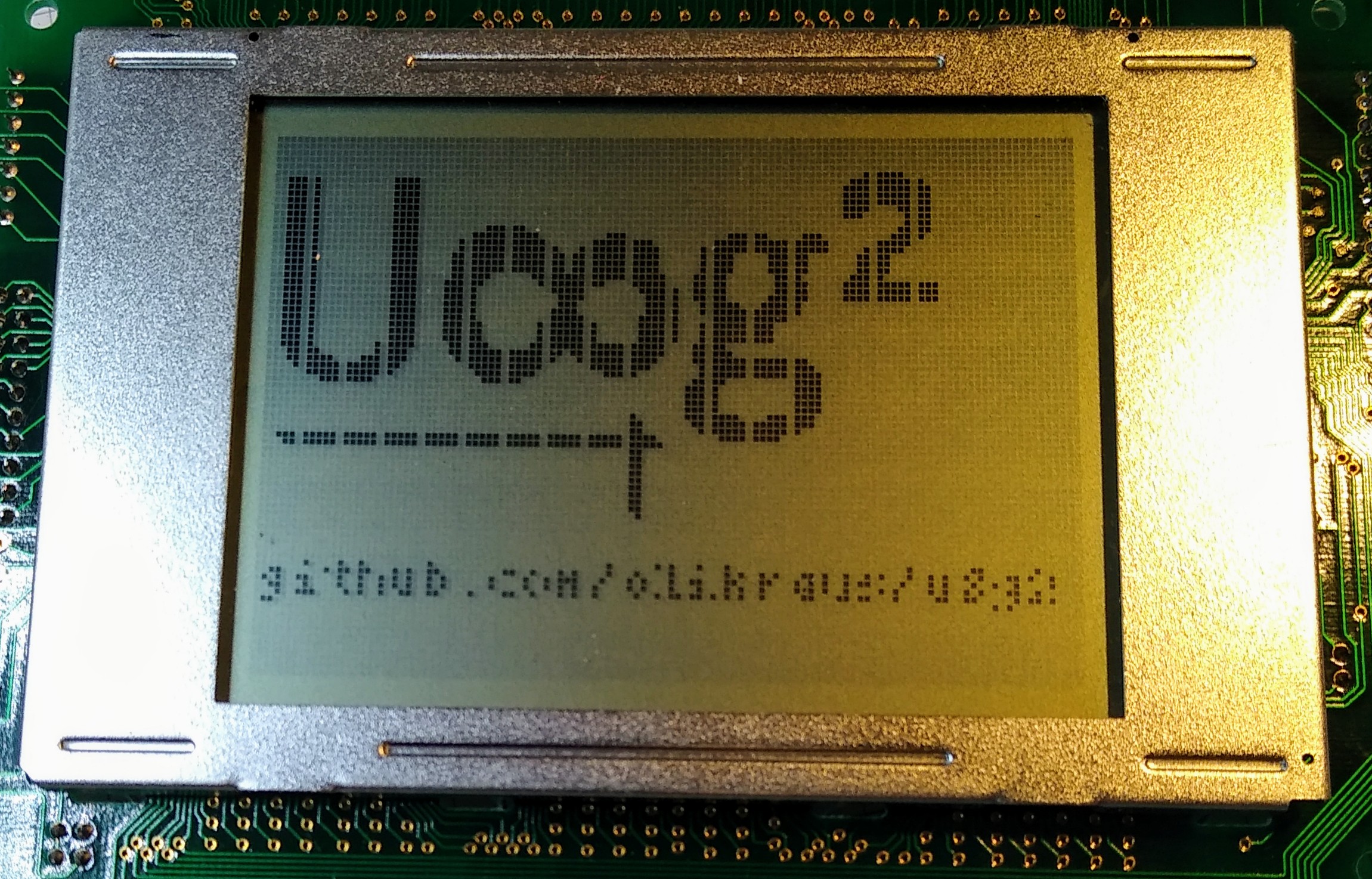
IMG_20210730_194809856

My own display is actually not a real graphics display, it trippls every 8th row and inserts an empty pixel every 6th column

@olikraus
Copy link
Owner

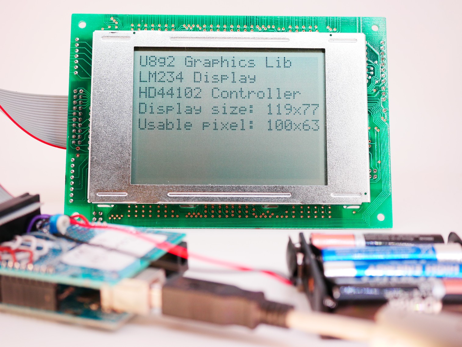
Another example. U8g2 seems to work so far...

1000592

@olikraus
Copy link
Owner

olikraus commented Jul 30, 2021

@spi5498 : I have created a new beta release 2.29.9. This release includes the constructor U8G2_T7932_150X32_1 in all of the example files. Can you test this with your display? Will something be visible?

You can download the latest U8g2 beta release from here: https://github.com/olikraus/U8g2_Arduino/archive/master.zip

  1. Remove the existing U8g2_Arduino library (https://stackoverflow.com/questions/16752806/how-do-i-remove-a-library-from-the-arduino-environment)
  2. Install the U8g2_Arduino Zip file via Arduino IDE, add zip library menu (https://www.arduino.cc/en/Guide/Libraries).

@ObligedTester
Copy link
Author

Wow, this is pretty exciting! I will try this out during the weekend and report back to you!

I see that my LCD module have a LMC7660 that is probably used to generate the VEE so thats why i couldnt find that when tracing the pinout.

@ObligedTester
Copy link
Author

Hello!

Did hook up the LCD today.
Unfortunately no luck with that.

I did confirm the connections once and they were correct from what I can find. Will need to confirm the pinout once more I guess!

not sure if there could be a tweak in the code necessary? There were no life at all

@olikraus
Copy link
Owner

olikraus commented Aug 2, 2021

Maybe you can share some more details (pictures, wiring, etc) so that I can also support you to crosscheck your setup.

@ObligedTester
Copy link
Author

I do have it soldered up on a prototype shield for the uno, so not sure how visible that will be.
However, i wonder since i have RST pin on my module, if that needs to be handled in the code?

@ObligedTester
Copy link
Author

ObligedTester commented Aug 2, 2021

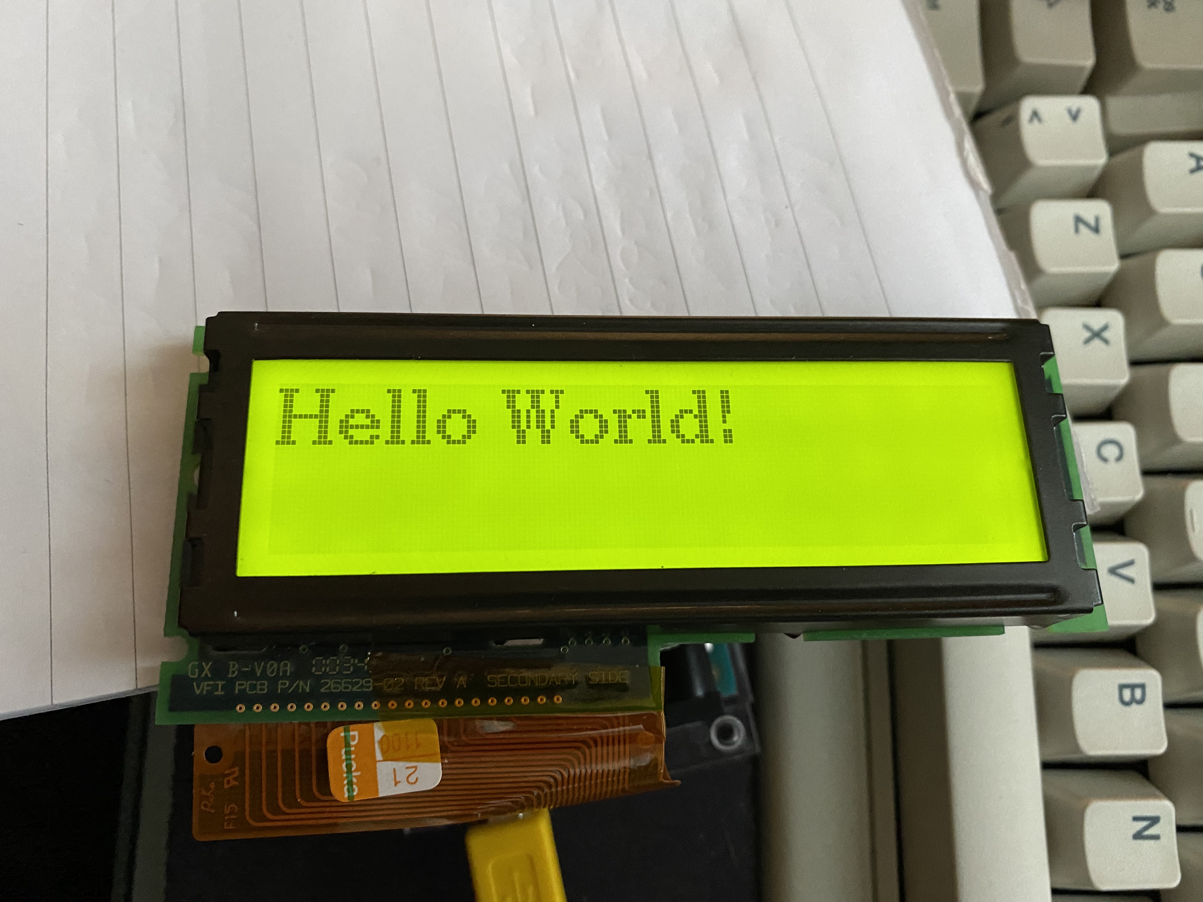
woho!

After some trial I found that RST needs to be set to high after power on, then it works!

just did it with a jumper wire manually, so need to add this to the code :)

this is very cool! Thank you so much for looking in to this!

@ObligedTester
Copy link
Author

479ED93A-F160-40ED-BC0B-4DD2D5571623

@olikraus
Copy link
Owner

olikraus commented Aug 2, 2021

Wow, looks great.
Reset pin: You can connect the reset input of your display to any unused GPIO pin. Then pass the number of that GPIO pin as last argument to the u8g2 constructor.

@ObligedTester
Copy link
Author

Yeah it is really nice!
Great to see it alive.

Aha! So reset is already implemented in the code for this? Cool!

will also count all the available pixels(width and height) impossible without turning them on.
Haha!

@olikraus olikraus closed this as completed Sep 2, 2021
Sign up for free to join this conversation on GitHub. Already have an account? Sign in to comment
Labels
None yet
Projects
None yet
Development

No branches or pull requests

2 participants