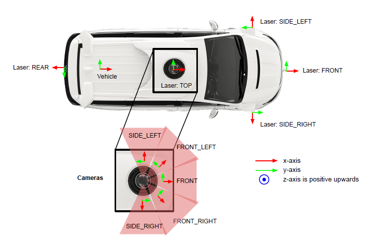
Waymo sensor setup and sensor configuration on Waymo’s autonomous vehicle:
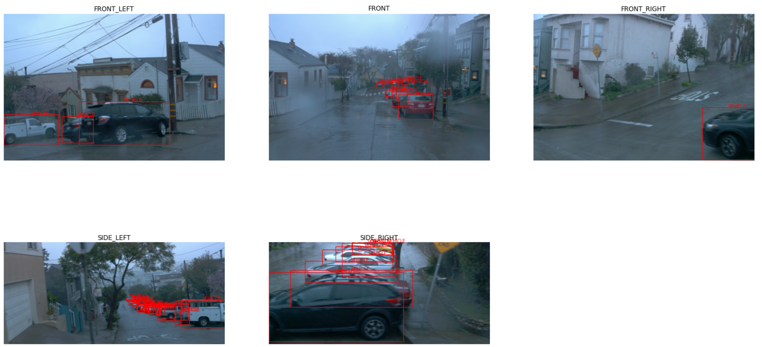
Dataset camera images are 1920x1280, which is equivalent to Ultra HD resolution and a horizontal field of view (HFOV) of +-25.2 degree. 2D bounding box labels in the camera images. The camera labels are tight-fitting, axis-aligned 2D bounding boxes with globally unique tracking IDs. The bounding boxes cover only the visible parts of the objects. The following objects have 2D labels: vehicles, pedestrians, cyclists. Waymo do not provide object track correspondences across cameras. Trains and trams are not considered vehicles and are not labeled. Motorcycles and motorcyclists are labeled as vehicles.
Top LiDAR covers a vertical field of view (VFOV) from -17.6 to 2.4 degrees, and its range is 75 meters and covers 360 degrees horizontally. Front, side left, side right, and rear LiDARs covers a relatively smaller area than the top LiDAR. They all include a vertical field of view (VFOV) from -90 to 30 degrees, and their range is 20 meters, which is smaller than the top LiDAR. The following objects have 3D labels: vehicles, pedestrians, cyclists, signs. 3D bounding box labels in lidar data. The lidar labels are 3D 7-DOF bounding boxes in the vehicle frame with globally unique tracking IDs. The bounding boxes have zero pitch and zero roll. Heading is the angle (in radians, normalized to [-π, π]) needed to rotate the vehicle frame +X axis about the Z axis to align with the vehicle's forward axis. Each scene may include an area that is not labeled, which is called a “No Label Zone” (NLZ). NLZs are represented as polygons in the global frame. These polygons are not necessarily convex. In addition to these polygons, each lidar point is annotated with a boolean to indicate whether it is in an NLZ or not.
The dataset contains data from five lidars (TOP = 1; FRONT = 2; SIDE_LEFT = 3; SIDE_RIGHT = 4; REAR = 5) - one mid-range lidar (top) and four short-range lidars (front, side left, side right, and rear). The point cloud of each lidar is encoded as a range image. Two range images are provided for each lidar, one for each of the two strongest returns. It has 4 channels: channel 0: range (see spherical coordinate system definition) channel 1: lidar intensity channel 2: lidar elongation channel 3: is_in_nlz (1 = in, -1 = not in)
message Label {
  // Upright box, zero pitch and roll.
  message Box {
    // Box coordinates in vehicle frame.
    optional double center_x = 1;
    optional double center_y = 2;
    optional double center_z = 3;

    // Dimensions of the box. length: dim x. width: dim y. height: dim z.
    optional double length = 5;
    optional double width = 4;
    optional double height = 6;

    // The heading of the bounding box (in radians).  The heading is the angle
    // required to rotate +x to the surface normal of the box front face. It is
    // normalized to [-pi, pi).
    optional double heading = 7;

    enum Type {
      TYPE_UNKNOWN = 0;
      // 7-DOF 3D (a.k.a upright 3D box).
      TYPE_3D = 1;
      // 5-DOF 2D. Mostly used for laser top down representation.
      TYPE_2D = 2;
      // Axis aligned 2D. Mostly used for image.
      TYPE_AA_2D = 3;
    }
  }

enum Type {
    TYPE_UNKNOWN = 0;
    TYPE_VEHICLE = 1;
    TYPE_PEDESTRIAN = 2;
    TYPE_SIGN = 3;
    TYPE_CYCLIST = 4;
  }
dataset.proto contains the major definition of CameraName, LaserName, Context, Frame, RangeImage, CameraLabels, Laser, Frame
message CameraName {
  enum Name {
    UNKNOWN = 0;
    FRONT = 1;
    FRONT_LEFT = 2;
    FRONT_RIGHT = 3;
    SIDE_LEFT = 4;
    SIDE_RIGHT = 5;
  }
}
message LaserName {
  enum Name {
    UNKNOWN = 0;
    TOP = 1;
    FRONT = 2;
    SIDE_LEFT = 3;
    SIDE_RIGHT = 4;
    REAR = 5;
  }
}
message CameraCalibration {
  optional CameraName.Name name = 1;
  // 1d Array of [f_u, f_v, c_u, c_v, k{1, 2}, p{1, 2}, k{3}].
  // Note that this intrinsic corresponds to the images after scaling.
  // Camera model: pinhole camera.
  // Lens distortion:
  //   Radial distortion coefficients: k1, k2, k3.
  //   Tangential distortion coefficients: p1, p2.
  // k_{1, 2, 3}, p_{1, 2} follows the same definition as OpenCV.
  // https://en.wikipedia.org/wiki/Distortion_(optics)
  // https://docs.opencv.org/2.4/doc/tutorials/calib3d/camera_calibration/camera_calibration.html
  repeated double intrinsic = 2;
  // Camera frame to vehicle frame.
  optional Transform extrinsic = 3;
  // Camera image size.
  optional int32 width = 4;
  optional int32 height = 5;
  .....

message LaserCalibration {
  optional LaserName.Name name = 1;
  // If non-empty, the beam pitch (in radians) is non-uniform. When constructing
  // a range image, this mapping is used to map from beam pitch to range image
  // row.  If this is empty, we assume a uniform distribution.
  repeated double beam_inclinations = 2;
  // beam_inclination_{min,max} (in radians) are used to determine the mapping.
  optional double beam_inclination_min = 3;
  optional double beam_inclination_max = 4;
  // Lidar frame to vehicle frame.
  optional Transform extrinsic = 5;

}
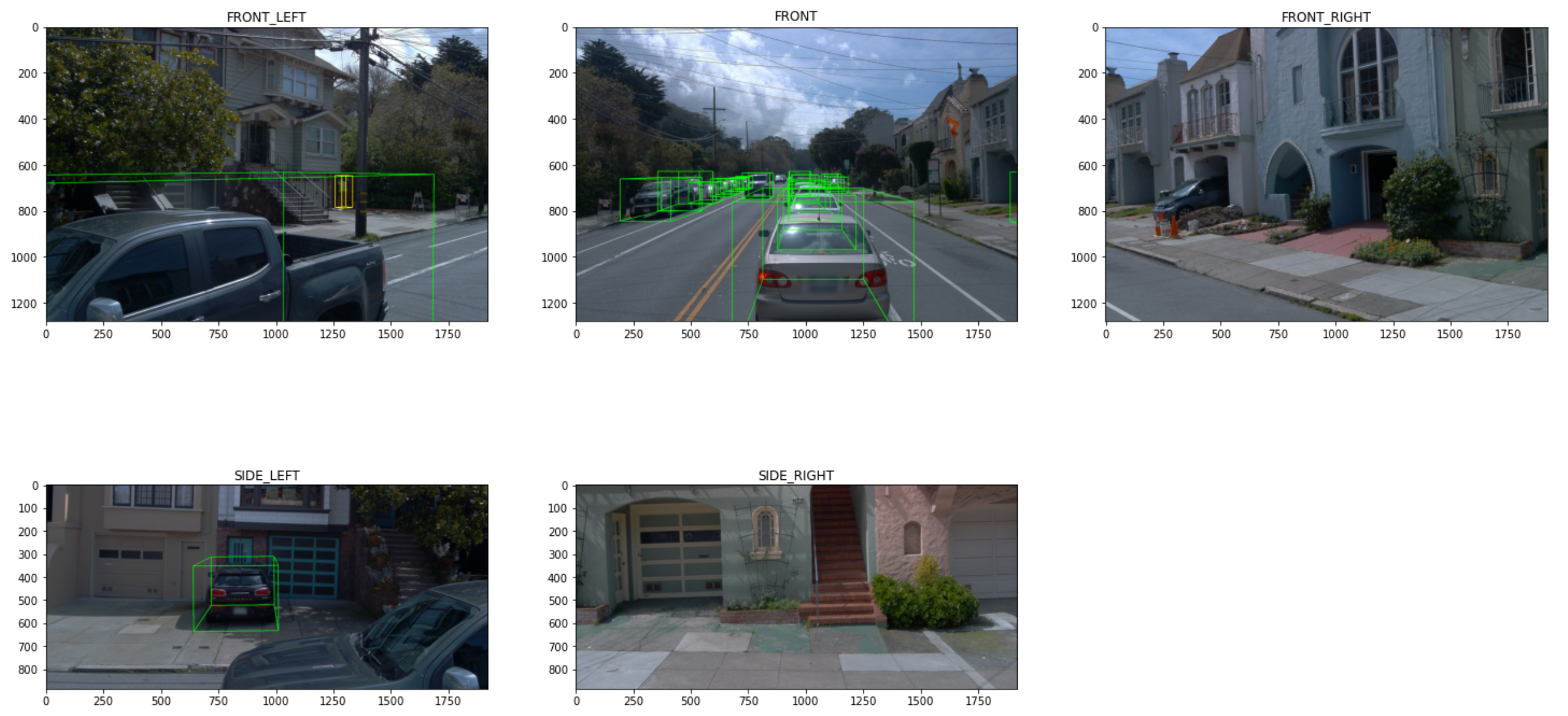
In WaymoStart.ipynb, get frame via "frame.ParseFromString(bytearray(data.numpy()))", img in frame.images, where frame definition is in WaymoStart.ipynb, images type is CameraImage. currentframe.camera_label.labels contains the 2D image labels. currentframe.projected_lidar_labels also contains the 2D bounding box. Function show_camera_image in WaymoStart.ipynb plots the 5 camera images:
Using the following code to get the range_images from frame, and convert to point cloud:
(range_images, camera_projections, range_image_top_pose) = frame_utils.parse_range_image_and_camera_projection(currentframe)
#convert_range_image_to_point_cloud
points, cp_points = frame_utils.convert_range_image_to_point_cloud(
    currentframe,
    range_images,
    camera_projections,
    range_image_top_pose,
keep_polar_features=True)Using Mayavi to visualize the Lidar bin file in WaymoKitti3DVisualizev2.ipynb:
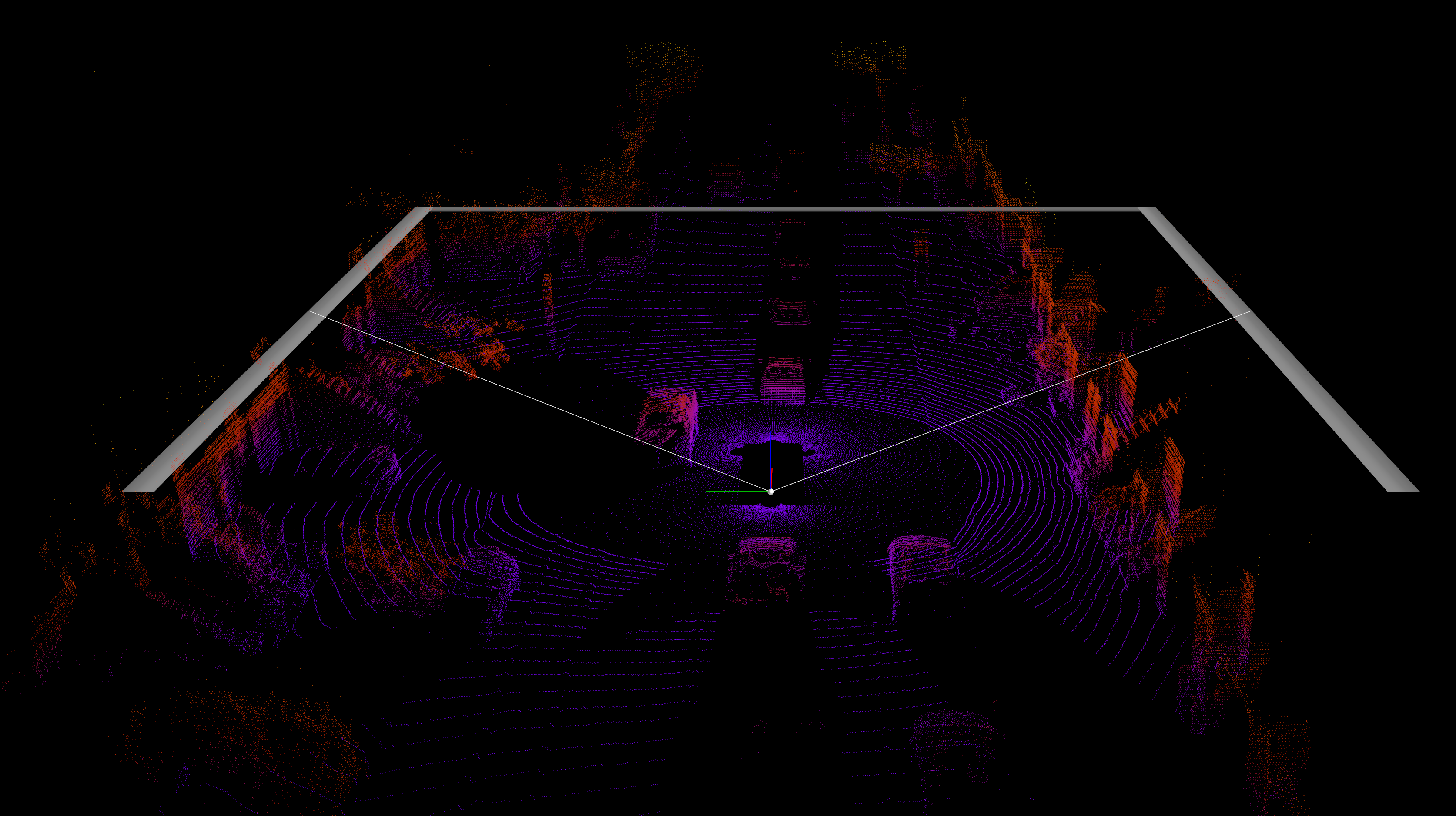
objectlabels is loaded from labels.txt file for all objects in 5 cameras. Load the labeled data from camera 0: object3dlabel=objectlabels[0], take the first object: box=object3dlabel[0]. box is Box3D class defined in Waymo.waymokitti_util. The following code takes an object and a projection matrix (P) and projects the 3d bounding box into the image plane.
import Waymo.waymokitti_util as utils
box3d_pts_2d, box3d_pts_3d = utils.compute_box_3d(box, calib.P[0])
compute_box_3d calculates corners_3d (8 corner points) based on the 3D bounding box (l,w,h), apply the rotation (ry), then add the translation (t). This calculation does not change the coordinate system (camera coordinate), only get the 8 corner points from the annotation (l,w,h, ry, and location t).
2D projections are obtained from project_to_image inside the utils.compute_box_3d
corners_2d = project_to_image(np.transpose(corners_3d), P)"

def project_to_image(pts_3d, P):
    n = pts_3d.shape[0]
    pts_3d_extend = np.hstack((pts_3d, np.ones((n, 1))))
    # print(('pts_3d_extend shape: ', pts_3d_extend.shape))
    pts_2d = np.dot(pts_3d_extend, np.transpose(P))  # nx3
    pts_2d[:, 0] /= pts_2d[:, 2]
    pts_2d[:, 1] /= pts_2d[:, 2]
    return pts_2d[:, 0:2]
project_to_image calculates projected_pts_2d(nx3) = pts_3d_extended(nx4) dot P'(4x3). The project result is the 2D bounding box in the image coordinate.
In the following code, use the project_rect_to_velo to convert the 3D bounding box (in camera coordinate) to 8 corner points to velodyne coordinate.
box3d_pts_3d_velo = calib.project_rect_to_velo(box3d_pts_3d)
# convert 3Dbox in rect camera coordinate to velodyne coordinate
def project_rect_to_velo(self, pts_3d_rect, camera_id):
    """ Input: nx3 points in rect camera coord.
        Output: nx3 points in velodyne coord.
    """
    pts_3d_ref = self.project_rect_to_ref(pts_3d_rect)# using R0 to convert to camera rectified coordinate (same to camera coordinate)
    return self.project_ref_to_velo(pts_3d_ref, camera_id)#using C2V
box3d_pts_3d_velo can be used as the 3D bounding box drawn on Lidar figure. For example, the camera 0's label 3D box shown in lidar

When draw other 3D labels into the Lidar figure, we need to use ref_cameraid=0 in box3d_pts_3d_velo = calib.project_rect_to_velo(box3d_pts_3d, ref_cameraid), because all 3D labels are annotated in the camera 0 frame not the individual camera frame. The following figure shows all 3D bounding boxs from 5 camera labels to the lidar figure:
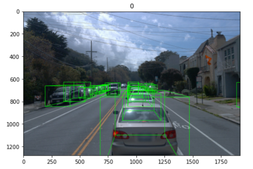
The box3d_pts_2d (8 points) returned from box3d_pts_2d, box3d_pts_3d = utils.compute_box_3d(box, calib.P[0]), can also draw 3D box (mapped to 2D) on image plane:
If we want to draw the 3D bounding box on other images (other than image 0), we need to do the following additional steps (basically, we first convert the 3D points in cam0 coordinate to velodyne, then convert to camID coordinate, finally project to imageID coordinate):
_, box3d_pts_3d = utils.compute_box_3d(obj, calib.P[camera_index]) #get 3D points in label (in camera 0 coordinate), convert to 8 corner points
box3d_pts_3d_velo = calib.project_rect_to_velo(box3d_pts_3d, ref_cameraid) # convert the 3D points to velodyne coordinate
box3d_pts_3d_cam=calib.project_velo_to_cameraid(box3d_pts_3d_velo,cameraid) # convert from the velodyne coordinate to camera coordinate (cameraid)
box3d_pts_2d=calib.project_cam3d_to_image(box3d_pts_3d_cam,cameraid) # project 3D points in cameraid coordinate to the imageid coordinate (2D 8 points)
The 3D bounding box in 5 images is shown in the following figure:
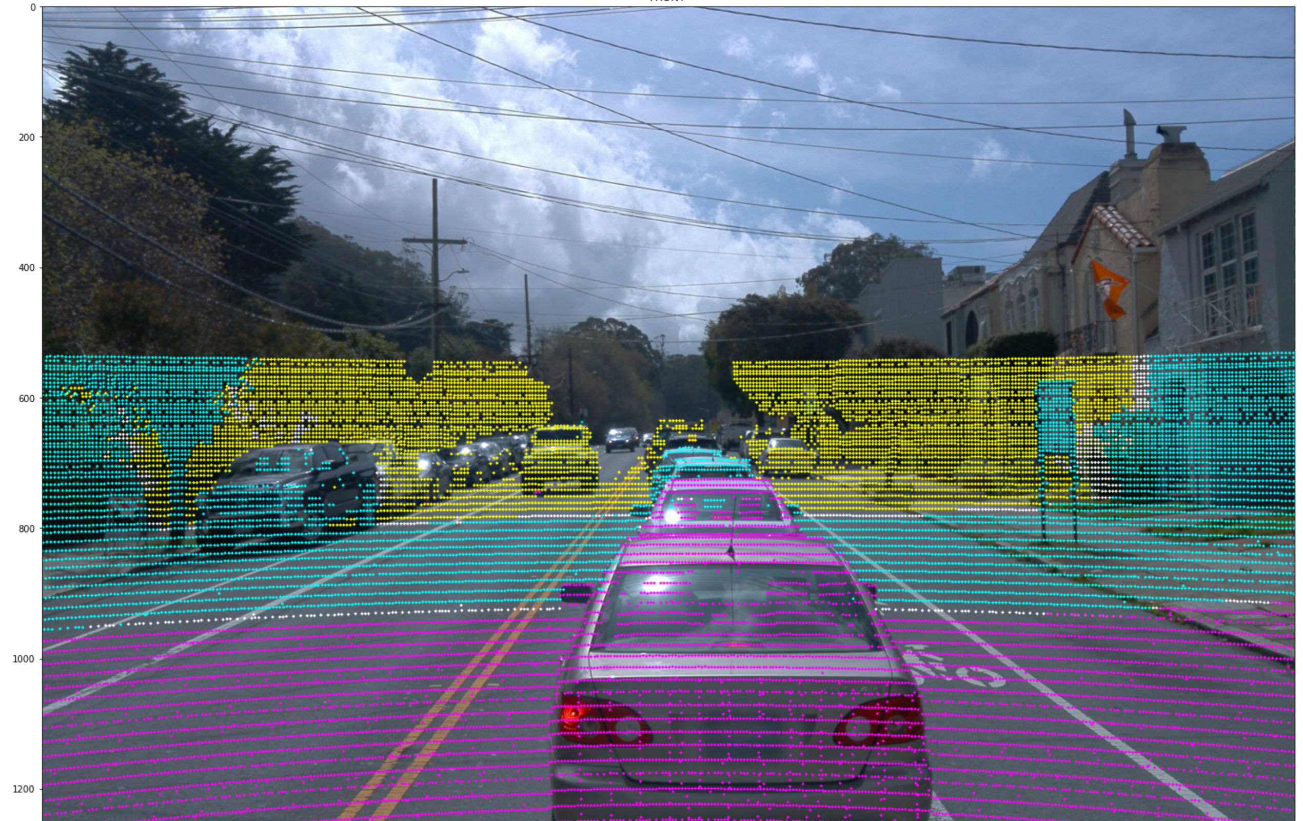
Project the lidar data to the 2D image needs the following key steps: 1) project_velo_to_image and only take points in image width and height, 2) use imgfov_pc_rect=calib.project_velo_to_cameraid_rect to convert velodyne points to cameraid coordinate (3D), the imgfov_pc_rect[i, 2] is the depth.
waymoframe2dict.py converts Frame proto into np dictionary to meet the requirements of Waymo realtime inference Latency
The first step in waymoframe2dict.py, convert tf record file to frames dictionary (the key is the frame_timestamp_micros), there are 199 frames each tf record file.
framesdict = extract_onesegment_toframe(fileidx, data_files, step)Use "convert_frame_to_dict" to convert the frame to dictionary
framedict=convert_frame_to_dict(frame)The keys, shapes, and data types are:
    POSE: 4x4 float32 array
    For each lidar:
      <LIDAR_NAME>_BEAM_INCLINATION: H float32 array
      <LIDAR_NAME>_LIDAR_EXTRINSIC: 4x4 float32 array
      <LIDAR_NAME>_RANGE_IMAGE_FIRST_RETURN: HxWx6 float32 array
      <LIDAR_NAME>_RANGE_IMAGE_SECOND_RETURN: HxWx6 float32 array
      <LIDAR_NAME>_CAM_PROJ_FIRST_RETURN: HxWx6 int64 array
      <LIDAR_NAME>_CAM_PROJ_SECOND_RETURN: HxWx6 float32 array
      (top lidar only) TOP_RANGE_IMAGE_POSE: HxWx6 float32 array
    For each camera:
      <CAMERA_NAME>_IMAGE: HxWx3 uint8 array
      <CAMERA_NAME>_INTRINSIC: 9 float32 array
      <CAMERA_NAME>_EXTRINSIC: 4x4 float32 array
      <CAMERA_NAME>_WIDTH: int64 scalar
      <CAMERA_NAME>_HEIGHT: int64 scalar
Among all keys, FRONT_IMAGE: <class 'numpy.ndarray'>, (1280, 1920, 3); TOP_RANGE_IMAGE_FIRST_RETURN is <class 'numpy.ndarray'> (64, 2650, 6), HxWx6 The six channels are range, intensity, elongation, x, y, and z. The x, y, and z values are in vehicle frame.
The lidar spherical coordinate system is based on the Cartesian coordinate system in lidar sensor frame. A point (x, y, z) in lidar Cartesian coordinates can be uniquely translated to a (range, azimuth, inclination) tuple in lidar spherical coordinates.
Use the following code to convert Waymo dataset to Kitti format (it calls converter.concurrenttaskthread()). HPC can open up to 56 (total CPU cores) threads for parallal conversion, 48 threads are tested:
DatasetTools]$ python Waymo2KittiAsync.pyThe conversion takes more than 48 hours (the maximum timeout of our HPC GPU node). You can record the finished file index, and continue the conversion from this index via startingindex metric. The converted folder is in
(venvpy37cu10) [010796032@g4 DatasetTools]$ ls /data/cmpe249-f20/WaymoKittiAsync/training/
calib  image_0  image_1  image_2  image_3  image_4  label_0  label_1  label_2  label_3  label_4  label_all  pose  velodyne
Create train val split file:
(venvpy37cu10) [010796032@g5 DatasetTools]$ python mycreatewaymoinfo.py --createsplitfile_only
Root path: /data/cmpe249-f20/WaymoKittitMulti/trainall/training
out_dir path: /data/cmpe249-f20/WaymoKittitMulti/trainall/
Total images: 175493
Train size: (140394, 1)
Val size: (35099, 1)
Done in /data/cmpe249-f20/WaymoKittitMulti/trainall/ImageSets/trainval.txt
Done in /data/cmpe249-f20/WaymoKittitMulti/trainall/ImageSets/train.txt
Done in /data/cmpe249-f20/WaymoKittitMulti/trainall/ImageSets/val.txt
Use the following code to generate info .pkl files:
(venvpy37cu10) [010796032@g5 DatasetTools]$ python mycreatewaymoinfo.py --createinfo_only
Root path: /data/cmpe249-f20/WaymoKittitMulti/trainall/
out_dir path: /data/cmpe249-f20/WaymoKittitMulti/trainall/
Generate info. this may take several minutes.
Generate info. this may take several minutes.
[>>>>>>>>>>>>>>>>>>>>>>>>>>>>>>>>>>>>>>>>>>>>>>>>>>] 140394/140394, 6.9 task/s, elapsed: 20461s, ETA:     0s
Waymo info train file is saved to /data/cmpe249-f20/WaymoKittitMulti/trainall/waymo_infos_train.pkl
[>>>>>>>>>>>>>>>>>>>>>>>>>>>>>>>>>>>>>>>>>>>>>>>>>>] 35099/35099, 8.0 task/s, elapsed: 4376s, ETA:     0s
Waymo info val file is saved to /data/cmpe249-f20/WaymoKittitMulti/trainall/waymo_infos_val.pkl
[>>>>>>>>>>>>>>>>>>>>>>>>>>>>>>>>>>>>>>>>>>>>>>>>>>] 175493/175493, 6.7 task/s, elapsed: 26166s, ETA:     0s
Waymo info trainval file is saved to /data/cmpe249-f20/WaymoKittitMulti/trainall/waymo_infos_trainval.pkl
The generated files are located in
ls /data/cmpe249-f20/WaymoKittitMulti/trainall
ImageSets  training  waymo_infos_train.pkl  waymo_infos_trainval.pkl  waymo_infos_val.pkl
After the infos.pkl files have been generated, you can go to mymmdetection3d to perform groundtruth db generation.
- WaymoStartHPC.ipynb is modified based on Waymo official sample and added bounding box visualization of the original Waymo Dataset (TFRecord format)
- WaymoNewtoCOCO.ipynb is the code to convert the original Waymo Dataset (TFRecord format) to COCO format. But, this jupyter file is not used in the latest version
- To enable parallel conversion of the Waymo TF record file to COCO format, we divide the conversion process into two parts: 1) Waymo2COCO.py parses WaymoTF record file and save the data as python pickle files; 2) combineWaymoCOCOpicklestoJsonxxx.py merges these created python pickle files to COCO format (.json annotation).
- Tensorflow2-objectdetection-waymodata.ipynb colab version is the Google Colab sample code to perform object detection and training based on Tensorflow2 object detection (latest version) and utilize the converted Waymo TFRecord file in Google Cloud storage.
- create_waymo_train_tfrecord.py and create_waymo_val_tfrecord.py under the DatasetTools folder are used to convert the original Waymo Dataset (TFRecord format) to TFRecord files used for Tensorflow object detection
- Folder tfobjectdetection under 2DObject folder contains Tensorflow2 object detection training, testing, evaluation, and export to TF-Lite code
- The sample code to play with Torchvision in Colab: colab link (you need to use SJSU google account to view)
- WaymoTrain.ipynb is the sample code to perform object detection training based on Torchvision FasterRCNN based on the original Waymo Dataset (TFRecord format), no dataset conversion is used in this sample code, but the parsing of the Waymo TFRecord file takes a long time.
- WaymoEvaluation.ipynb is the sample code to perform evaluation (both COCO evaluation and image visualization) of the trained object detection model based on Torchvision FasterRCNN
- coco_eval.py, coco_utils.py, engine.py, transforms.py, utils.py under the folder of MyDetector are copied from Torchvision directory and used in the WaymoTrain.ipynb and WaymoEvaluation.ipynb
- torchvision_waymococo_train.py is the new version that performs Pytorch FasterRCNN training based on converted Waymo COCO format data. This version can be applied for any dataset with COCO format annotation, it also avoids the paring of the Waymo TFRecord file every time.
- WaymoDetectron2Train.py is the code to run training based on Detectron2. This code used the COCO formated dataset (WaymoDataset converted to COCO via WaymoNewtoCOCO.ipynb)
- WaymoDetectron2Evaluation.ipynb is the jupyter notebook code to run evaluation based on Detectron2
- WaymoCOCODetectron2train.py is the new version of Detectron2 training, WaymoCOCODetectron2eval.py is the evaluation code
- mymmdetection2dtrainxxx is the code to train mmdetection2d model for the Waymo dataset
- Folder dockersubmission contains waymo 2D detection submission related code.
- Folder wod_latency_submission contains the library of our 2D object detector for inference evaluation. We included Detectron2, Tensorflow2, Torchvision, and mmdetection2d models.
