acousticOFDM is an simple acoustic implementation of OFDM-modulated communication. Two android phones are used to play and record the acoustic signal and transmit bits information. Current main branch is a refactor of the legacy implementation, which optimizes the main modulation part and adds IQ mod/demod in the transceiver. The legacy implementation has low spectrum efficiency and limits the throughput of OFDM transmission.
mainbranch contains the new IQ-based implementation of acousticOFDM. FolderMatlabcontains MATLAB implementation, wheremain_tx.mandmain_rx.mare the entrances for sender signal generation and receiver signal processing, respectively. FolderAudioTransceivercontains the Android Studio project for audio signal transmitter and receiver. The program is only used to play the MATLAB-generated signal and record the received signal. It does not contain any modulation and demodulation implementation. FolderFigurescontains some figures for this Readme.legacybranch contains the legacy implementation and maybe some archived functions. In this branch, folderMatlabalso contains the MATLAB OFDM modulation and demodulation. FolderasonicOFDMis the legacy Android implementation of the whole transmitting and receiving process. Different frommainbranch, it contains the signal generation, modulation, and demodulation. However the implementation is pretty old and has limited throughput as discussed above.
OFDM (Orthogonal Frequency Division Multiplexing) uses multiple closely spaced orthogonal subcarrier signal to carry bits data in parallel. It is commonly used in today's RF transceivers. Detailed explanation of OFDM can be found easily and we will not go into the details here.
In an RF transmitter, the whole process of OFDM is shown below:
The digital signal processing part is commonly seen in all types of OFDM modulators. It output the digital baseband IQ signal
The OFDM receiver for RF is shown below:
As we can see, It almost simply inverts the modulation process for a transmitter. Differently, it contains the RF low pass filter to filter out the baseband signal and remove
For an acoustic implementation, it is easy to see that we can simply keep the digital processing part same with the RF implementation. In other words, the baseband processing is directly used. However, the main difference for RF and acoustic system is their frontends. RF transceivers use circuit to process the analog signal, e.g., mixers, filters, phase shifters. For acoustic systems, what we get is usually the sampled in-air signal in digital form. For example, a microphone samples the sound signal in 48000Hz and directly feeds the digital form samples to us. Therefore, to connect the baseband part of commonly seen OFDM modulators/demodulators with the acoustic frontend, we need to simulate the IQ modulation in digital form. In a transmitter, such a process is shown below:
We can see that there is not any DAC part. It is replaced by a resample part. The frontend part, however, has little difference. It merely simulates the process in RF transceivers. To understand why the resample part exists, we need some specific sampling configurations. For example, we let the sampling frequency for baseband signal be 4000Hz, the sampling frequency for sound wave be 48000Hz. To conduct the digital mixing process, we need to multiply the baseband with
Correspondingly, the process of an receiver is shown below:
It is very similar with Tx part, only the resample process is a downsampling now.
We give some design details of acousticOFDM.
The packet contains an STF (short training field), an LTF (long training field), and some data symbols. Each of the symbol lasts for 20ms, since the baseband sampling frequency is 4000Hz and every symbol is 80 points long. The packet structure is similar to WiFi OFDM packet but much simpler.
The STF is used for frame synchronization. It contains 5 periodic signal sequence which is the same for WiFi STF but in half length. The definition for WiFi STF is:
The LTF is used for the receiver to estimate the channel and compensate for data symbols. The definition is also the same with WiFi LTF but in half length. The definition for WiFi LTF is:
We use 64 length FFT and 52 of which are used to transmit data, also the same with WiFi. The mapping between subcarrier numbers and its position in FFT is shown below:
We use the simplest Least Squares (LS) channel estimation, which simply takes the result of the received signal on certain subcarrier dividing the transmitted signal. It can be improved using other method.
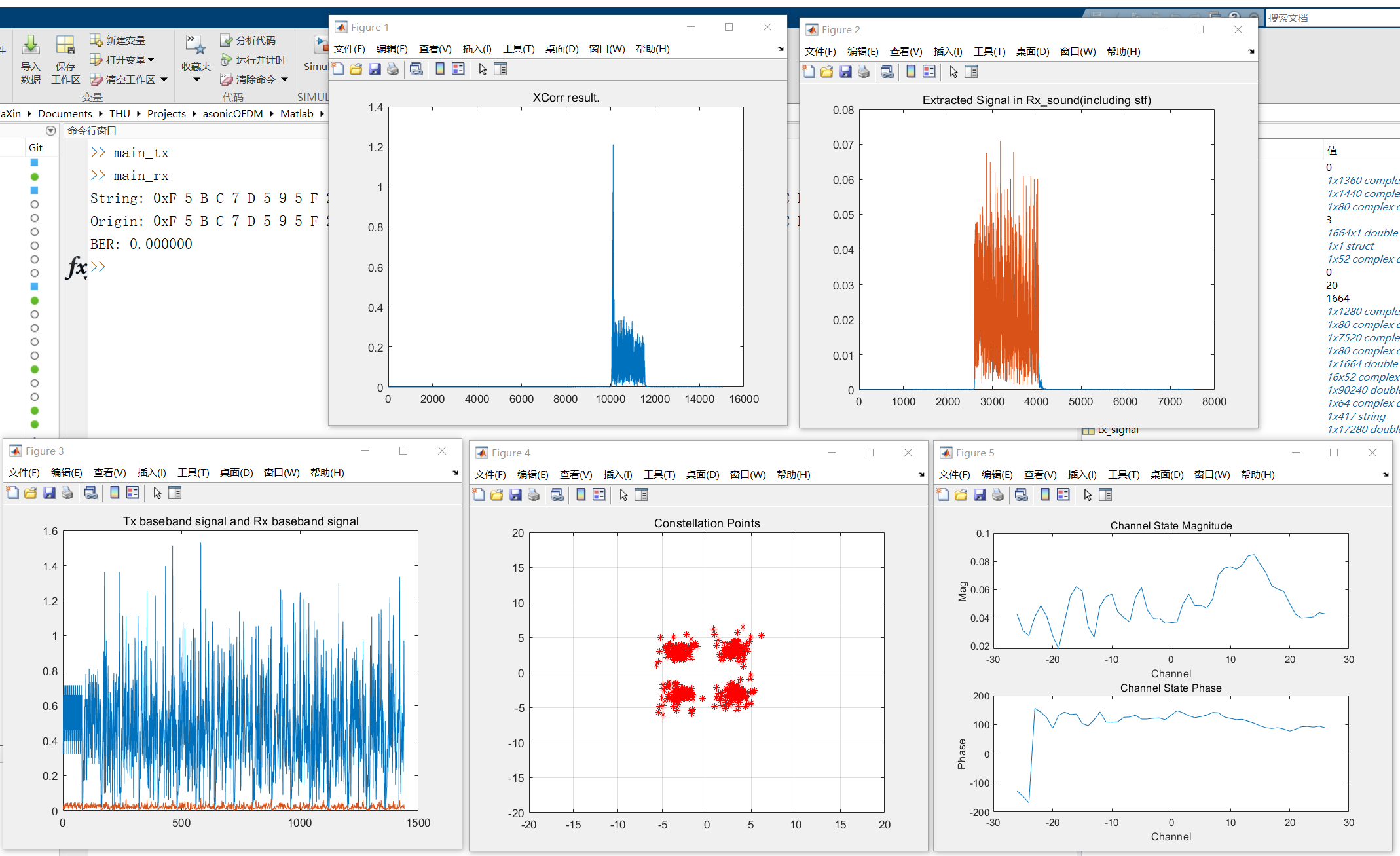
We show the result of one reception here:
[1] Molisch, Andreas F. Wireless communications. John Wiley & Sons, 2012.
[2] Tse, David, and Pramod Viswanath. Fundamentals of wireless communication. Cambridge university press, 2005.
[3] "IEEE Standard for Information Technology - Telecommunications and Information Exchange Between Systems - Local and Metropolitan Area Networks - Specific Requirements - Part 11: Wireless LAN Medium Access Control (MAC) and Physical Layer (PHY) Specifications", in IEEE Std 802.11-2007 (Revision of IEEE Std 802.11-1999), 2007.
